Teradata relies on four architectural components
- Parsing Engine(PE) or Optimizer
- Access Module Processors(AMPs)
- BYNETs
- Disks
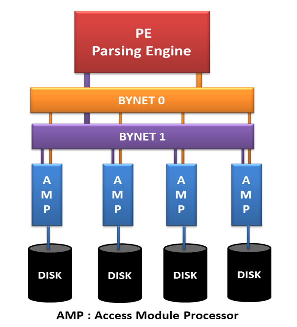
Parsing Engine
A Parsing Engine (PE) is a virtual processor (vproc). It is a component that interprets SQL request, receives data add pass it. It is made up of the following software components:
- Session Control
- Parser
- Optimizer
- Dispatcher
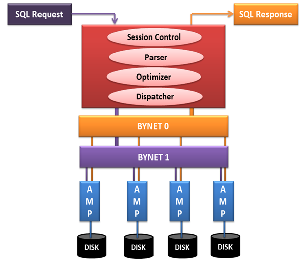
Each PE can support a maximum of 120 sessions.
Session Control
It verifies the request for session authentication (username, password) and either allow or disallow the request it is termed as logon function. When any ongoing activity is terminated then it is termed as logoff.
Parser
It interprets the receive SQL request, check statement for syntax and semantics. And consult data dictionary to ensure that requested object exist and user has authority to access those objects.
Optimizer
It is responsible to create a least expensive plan (in terms of time), to return the requested data. To get maximum output with minimum resource contention. Optimizer must know system configuration, availability of units of parallelism (AMPs & PEs) and the data demographics.
Data Demographics
It visually depicts the demographics of a selected table, its sub-tables and statistics of its stat field.
Dispatcher
It controls the sequence in which the steps is to be executed on system. And passes the steps on to BYNET.
It is composed of execution control and response control. Execution control receives steps from parser and send it to AMPs for processing, receives status report from AMPs. When AMPs have completed processing, it passes the report to response control. Response control passes that report to user.
BYNET
The BYNET gets its name from the Banyan tree. The Banyan tree has the ability to continually plant new roots to grow forever. Likewise, the BYNET scales as the Teradata system grows in size. All communication between PEs and AMPs is done via the BYNET. When the PE dispatches the steps for the AMPs to perform, they are dispatched onto the BYNET. The messages are routed to the appropriate AMP(s). Each AMP or PE can use one BYNET to retrieve communication and simultaneously accept messages using the other BYNET. Both BYNETs can be used to send a message or to receive a message.
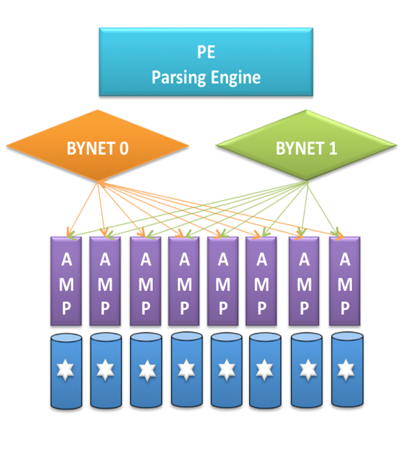
Features of BYNET
Fault Tolerant
If any of the BYNETs (0 or 1) fails other took its place. If there is any unusable path in either of the networks, it will automatically reconfigure that network so that all message avoid unusable path. Additionally, in the rare case that BYNET 0 cannot be reconfigured, hardware on BYNET 0 is disabled and messages are re-routed to BYNET 1.
Load Balance
Traffic will be automatically and dynamically distributed between both the BYNETs.
Scalable
As you add more nodes to the system, the overall network bandwidth scales linearly. This linear scalability means you can increase system size without performance penalty — and sometimes even increase performance.
High Performance
An MPP system typically has two BYNET networks (BYNET 0 and BYNET 1). Because both networks in a system are active, the system benefits from having full use of the aggregate bandwidth of both the networks.
The BYNET technology makes Teradata parallelism possible.
AMP
The PE passes the PLAN to the AMPs over the BYNET. The AMPs then retrieve the rows they own from their disks and pass it back to the PE over the BYNET. When a table is first created each AMP creates a table header on their disk. Even though the table is empty the AMPs at least know the table name, the columns in the table, and any indexes the table. When the table is loaded each AMP receives rows for that table that they and only they own. They carefully place the rows inside data blocks where they can easily be retrieved. Now each AMP will own their own Table Header for the table and they will also own data blocks where they place the rows for that table.
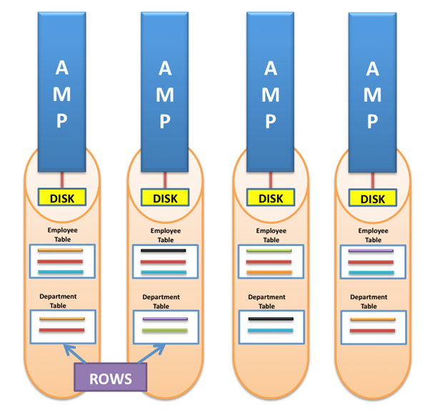
Teradata took every table and spread the rows across all the AMPs in the system and the birth of parallel processing happened.
Disk
Disks are the physical storage where actual data is stored. Each AMP has its own attached disk from where it write or reads data.
Images Source – Internet
